 Home |
  Links&Readings |
Browse by Subject (alphabetical) |
Maintenance Projects
Links&Readings |
Browse by Subject (alphabetical) |
Maintenance Projects
A relay (also known as electro magnetic switch) puts into contact two circuits : it is a system of two independent circuits
inside a box. Inside a relay there is a coiled wire which, when it is
prompted by electricity, produces a magnetic field and this magnetic
field pulls magnetically a set of contacts that make the current pass
in the other circuit.
In general, relays are used to connect a low amperage circuit
(using a wire with a small gauge) and a hight amperage circuit. This is
very well explained in this article "Relay Basics" by Chet Walters.
The coil or the contacts can fail inside a relay.
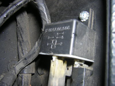
One way of testing a faulty relay is, while the relay is still in
place, to squeeze manually the relay in order to make the contact work
and see if the device operating after the relay works properly.
If the test is positive so the device itself is not faulty, but the relay
There are four parts in a relay (low amperage coil circuit and hight amperage load circuit):
What happens when you activate a relay ?
On the first circuit, when you (1) switch the horn button, you activate
an electric field into the coil (2) and this shuts down the relay
switch on the second circuit (3), allowing the horn to blow (4).
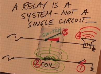
Screen shot from the video by Daniel Sullivan on Youtube
Testing a relay with a 9V battery
It is possible to check whether a relay clicks or not using a 9V battery.
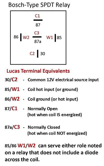
Testing the entire system from a relay

You see that from a relay, the two circuits are pretty inaccessible but they can be diagnosed.
There are two voltage readings and two ohms readings.
| Pin number | Measure |
| #30 | 12V |
| #85 | 12V |
| #87 | Ohm value of the device |
| #86 | 0 Ohm when closed / 1 when open |
Depending on the car model there are 6 to 10 relays and they are
From RR forum Australia
I have several lethargic devices -- front passenger window, front passenger door lock, windshield wipers, and others.
I think the common element is a relay and I suspect that I am losing voltage due to worn or coated contacts.
A first method consists in reading the relay section of the
electrical manual (M10). Here you'll find the types, location and
function of the relays
housed under the relay bank which is inside the bonnet just facing the driver.
For those relays which are not listed in this document, one must use
the wiring diagram (for RH car > VIN 13681 see page 274 of the
Wiring Diagram part of the Workshop Manuals).
And on this diagram, check for the colours of the wires that are feeding the relay.
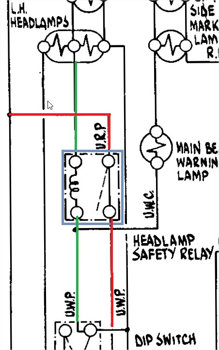 Here for example you read that the headlamps security relay is feeded
on the low amperage side by a UWP (Blue White Purple) wire
Here for example you read that the headlamps security relay is feeded
on the low amperage side by a UWP (Blue White Purple) wire
and on
the hight amperage circuit by a BWP wire on the ground side and a URP
(Blue Red Purple) wire on the load side towards the lamps.
