 Home |
  Links&Readings |
Browse by Subject (alphabetical) |
Maintenance Projects
Links&Readings |
Browse by Subject (alphabetical) |
Maintenance Projects
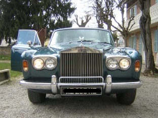
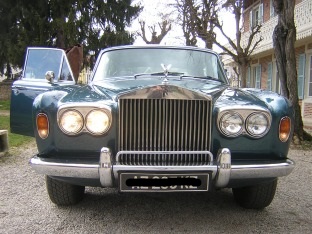
Inside Left #1 (seen facing car) light doesn't lit
Outside Right #3 light doesn't lit on high beam
|
|
|
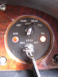
| Position for testing | Headlamps | High beam (foot dip switch) |
This is an excerpt from RR forum Australia
"The headlamp flasher was not working on my 1975 SS1. I just traced
the fault to a faulty flasher relay.
The relay was clicking but the contacts had bunt out and were not
making contact.
This got me thinking about why they had burnt out, and it has raised
some interesting questions.
The most obvious question is
why Rolls-Royce didn't put a relief relay in the Main Beam
supply, instead of feeding
the entire current for all 4 headlamps through the Switchbox, Dip
Switch, Flasher Relay, and other components.
Considering the number of relays in this car (some of dubious purpose)
it's hard to understand why they didn't put one in the main headlamp
supply - especially as the car has 4 headlamps.
I looked in the handbook, and the specified (UK) headlamps at the time
were 37.5W/60W sealed beams for the outer ones, and 75W for the inner
ones.
So the 4 original main beams
consumed a total of 270W. At 12 volts, that is a current of 22.5
Amps(1). All 4 headlamps are fed through Fuse 4, which is a wire fuse
of only 22A.
How is this possible without blowing the fuse continually? Are my
calculations wrong? Even with 4 modern halogen headlamps of only 60W,
the current would be 20A, which is much too near to the nominal value
of the fuse for comfort.
No wonder they needed to add a Headlamp
Safety Relay to switch back to dipped beams if fuse 4 blew. That
looks almost inevitable! It would have made more sense to use this
relay to power the inner headlights via fuse 5 and share the headlamp
load between fuse 4 and fuse 5 (fuse 5 feeds the headlamp flasher
circuit)."
(1) Ohm's law : E (volts); I (current in amps); R (resistance in ohms); P (power in watts)
E = I x R or P=I x E
I = E ÷ R or I= P ÷ E
R = E ÷ I or E= P ÷ I
Wiring diagram
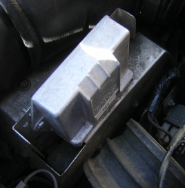 On top of the relay box sits the voltage regulator.
At first I've swapped inside lamps in order to check that they were
correctly operating and they were.
So for #1 the problem comes from the circuit.
