 5 relays fitted in the printed circuit board (PCB) to be found in the relay box attached to the bulkhead, SY 1976
 Home |
  Links&Readings |
Browse by Subject (alphabetical) |
Maintenance Projects
Links&Readings |
Browse by Subject (alphabetical) |
Maintenance Projects
Electrical problems can be sorted in two categories : "before relay" and "after relay". Relay themselves, as they connect two systems, are important places to look at when you
investigate electrical issues. They can be faulty (not so frequent), but also they are normally placed in reachable location from where it is possible to test the wiring connections before they dig into the body of the car.
The "relay" section of the Workshop Manual (M10) does list some relays and their applications, but this is far from exhaustive. In my case for example, the relay box (right hand side of the bulkhead) only shows
five relays, when they are supposed to be 6 according to the manual. Furthermore, the relays IDs listed in the WM table are not the actual one that I could find in my car.
Relays are fitted about everywhere in the car, so a thorough reading of the "good" wiring diagram is necessary, but here too, it is not enough. The relays locations are not given in the theoretical diagram, assuming that
you were able to find the one that matches your car. Not mentioning the diverse modifications your car would have come through during the last decades... But let's not loose optimism
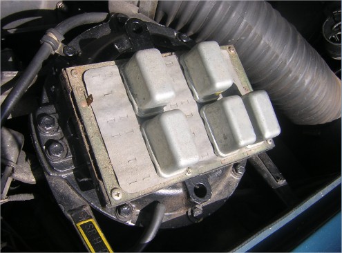
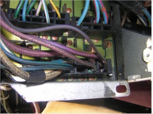
5 relays fitted in the printed circuit board (PCB) to be found in the relay box attached to the bulkhead, SY 1976
The wiring diagram - Assuming that the wiring diagram (for RH car > VIN 13681 see page 274 of the Wiring Diagram part of the Workshop Manuals) is a good starting base but not the best possible, because this document as it is available on the Australian RR technical library is dated 1973. My car is 1976.
The Workshop Manual -
The relays IDs
The wires colours
This document lists the following relays
| System | Relay name on WD | Description | Wiring |
| Starter motor | Starter Relay | (5 contacts, not marked) Operates the starter motor and solenoid | Brown Cotton - White Green Plastic - White Yellow Plastic |
| Parking | Auto Park Relay | (W1-W2 / C1-C2) Links the gear range selector switch and the ignition switch | Red Yellow Cotton -> W1; Red Green Plastic -> W2; Black Brown Plastic -> C1 |
| Warning lamps | Break Warning Lamp Test Relay | (W1-W2 / C1-C2-C4) | Green Plastic -> W1; Green Purple Plastic -> W2; Black -> C2; Yellow Green Plastic -> C4; White Green Plastic -> C1 |
| Warning lamps | Fuel Warning Lamp Dimming Relay | (W1-W2 / C3-C2) Linked to low fuel warning lamp and to fuse #7 | Black Plastic -> W1; Red Plastic -> W2; Green Plastic -> C2; White Purple Plastic -> C3 |
| Warning lamps | Coolant Warning Lamp Test relay | ((W1-W2 / C2-C3) Linked to Fuel Warning Lamp Dimming Relay on W1-W2 and to Coolant Probe, Coolant Level Amplifier | Green Plastic -> W1; Green Purple Cotton -> W2; Blue Green Plastic -> C2; Blue Green Plastic -> C3 |
| Stop Lamps | Stop Lamp Relay | (4-5-6 / 7-8) Linked to Stop Lamps; to Handbrake Micro Switch; to Stop Lamp Switch; to Dimming Relays | Black -> 8; White Green Plastic -> 4; White Green Plastic -> 6; Purple White Plastic -> 5; White Blue Plastic -> 7 |
| Hazard Warning | Hazard Warning Relay | (W1-W2 / C1-C2x2linked-C4) C2 linked to Hazard Warning Flashing Unit; W1 same; W2 ground; C1 to Direction Indicator Flasher Switch; C4 same | Green Brown Plastic -> W1; Black -> W2; Green Red cotton -> C1; Green Blue cotton -> C2 |
| Direction Indicators, Stop Lamps | Dimming Relay | (W1-W2 / 1-4 / 2-5 / 3-6 / 7-8 /9-10) linked to Stoplamp Switch; to rear, front, flashers and repeaters; W1 to hazard flasher unit and switch; W2 to ignition switch | Green Brown Plastic -> W1; Red Blue Cotton -> W2; Purple White Plastic -> 7,8,9,10 and 1; Green Black Cotton -> 2; Black White Cotton -> 3; White Purple Plastic -> 4; Green Red Cotton -> 5; Green White Cotton -> 6 |
| Hood | Hood Relay | (W1-W2 / C1-C2) linked to Hood Switch | White Cotton -> W1; Blue Brown Cotton -> W2; Green Plastic -> C1 |
| Head Lamps | Head Lamp Flash Relay | (W1-W2 / C1-C2) W1 linked to Head Flash Switch; W2 to fuse 5; C3 to Dip Switch then Head Lamp Safety Relay | Brown Blue Plastic -> W1; White Cotton -> W2; Blue White Plastic -> C3 |
| Head Lamps | Head Lamp Safety Relay | (4 contacts, not marked) Connected to Dip Switch, to Head Safety Cut Out, to Main Beam Warning Lamp, to (L) and (R) Head Lamps | Blue White Plastic; Blue Red Plastic; Blue White Cotton |
| Horn | Horn relay | (W1-W2 / C2-C3) W1 linked to horn button; C2 to fuse 3; C1 to horns | Purple Black Plastic -> W1; Purple Cotton -> C2; Purple Yellow Plastic -> C3 |
| Blower motor | Blower Motor Relay | (W1-W2 / C2-C3) linked to Blower Switch | Green Black Cotton -> W1; Green Cotton -> W2; Yellow Plastic -> C2 and C3 |
| Radio and Tape | Radio / Tape Change Over Relay PC | Contacts 1 to 12 | Purple Blue cotton; Slate Blue Plastic; Black |
| Speed Regulator | Speed Regulator Relay | (W1-W2 / C2-C3) Connects to Regulator | Black -> W1 and C2; White Purple Plastic -> W2; Purple White Cotton -> C3 |
| Air conditioning | Water Tap Relay 1 | (W1-W2 / C1-C2-C3) to Water Tap Actuator | White Red Plastic -> W1; Yellow Purple Plastic -> W2; White Purple Plastic -> C1; Green Plastic -> C2; White Yellow Plastic -> C3 |
| Air conditioning | Water Tap Relay 2 | (W1-W2 / C2-C3) to Compressor Clutch; to Heater Switch | Black -> W1; White Blue Plastic -> W2; Yellow Purple Plastic -> C2 White Red Plastic -> C3 |
| Seats | Electrically Operated Seats relays (LH) | (4 contacts, not marked); 2 symmetrical relays between motor and switch | Black Yellow Plastic / Black Blue Plastic |
| Seats | Electrically Operated Seats relays (RH) | (4 contacts, not marked); 2 symmetrical relays between motor and switch | Green Blue Plastic / Green Red Plastic |
We refer to section 10 of the WM starting page M63. The point is to check whether the parts mentioned in the WM apply to my car, in order to check for alteration or even missing items.
My car (June 1976) can be considered as "late refrigerated" as to this manual reprinted in nov 1976. Refrigerate means equipped with AC.
This document mentions a relay box connecting relays to the wiring loom through a printed circuit board (PCB) and also relays fitted apart from the PCB, behind the front cover of the relay box
1- Behind and on top the relay box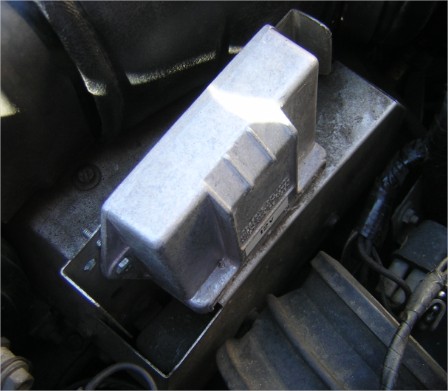
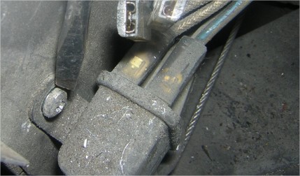
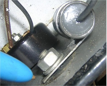
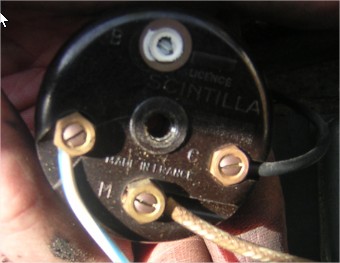
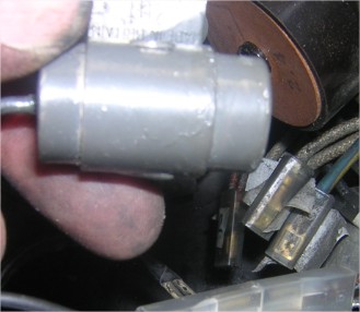
| There was also these two elements, mentioned in the WM : | a choke thermal delay switch (Scintilla) | a regulator capacitor |
 |
 |
 |
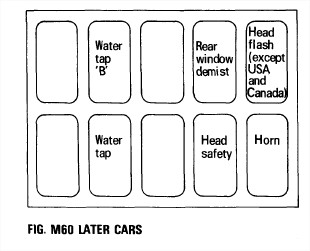
| Left is how the WM locates the relays | and right is my relay table | |
 |
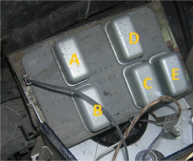 |
A is labelled 33298 - Alternator field B 33269 - ? C 33270(0) - Head Lamp, Safety ignition warning lamp and choke, Additional Water Tap and Rear Window Demister D 33270(0) E 33270(0) You can notice that only the relay marked C matches... |
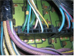
There are 5 connectors under to the PCB :
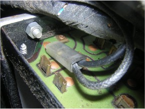 | Two connections : Black cotton, Black plastic : black is GROUND |
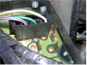 | Three connections (plastic) : White Purple, Green (FUSED IGNITION CONTROLED), White Yellow |
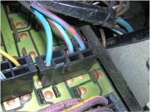 | Three connections (plastic) : Blue, Blue Red (double) |
 | Six connections (plastic) : Green black (double), Blue, White Purple, White Blue, Yellow Purple |
 | Six connections : Black Purple (plastic), Purple Yellow (plastic), Purple (cotton) double, Blue Black ((plastic) double, Blue White (pl astic), White (cotton) double |
