
Relay : repairing a faulty relay
When a device doesn't operate it can be the device itself, a bad grounding, a faulty wiring, a problem in the socket, a faulty relay, a faulty switch.. Here we have found a relay that didn't act properly during the tests. So we decided to open it and repaired the missing contact.

0-The issue I was tracking
With full headlamps on (high beam), only the two right handside lights were on (as you can notice on the picture).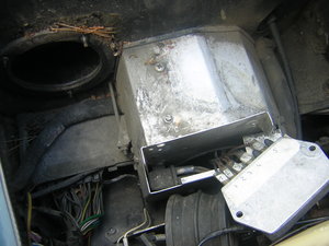
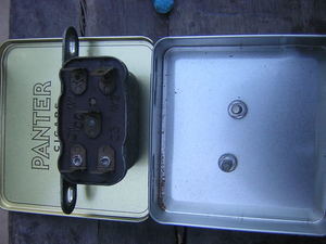
1-The relay to suspect is located next to the Voltage regulator
You can see it on the picture at the left handside of the regulator, secured to the relay board. 5 (or 6 depending on the model) relays are inside the box, this one rests outside.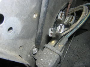
2-The relay is attached to the outside of the relay box by two philips screws
You can notice by its wiring (plastic blue-white) that this relay "has to do" with the high beam circuit. In my case this circuit was not operating on the left handside of the car. This relay is a 33222 F.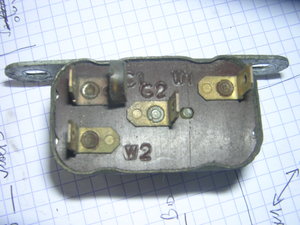
3-The relay terminals naming in general
6RA relays have various number of pins. Refer to the Workshop Manual to know how your relay is supposed to operate. But the W1 and W2 terminals are always the one feeding the coil. C2 is the fixed contact, C1, C3, C4 are the other contacts. The picture shows a four-pin relay, number 33209 J.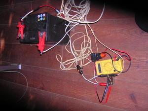
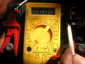
4-Testing the relay
To test a 6RA relay, feed the W2 pin vith 12V (red cable) and W1 with earth (black cable). Use a test cable with a fuse (15A) and a switch. I also fit a test light on W1 and W2 to make visualy sure that the coil is energized.There are TWO things to check :
1- Feeding the W1-W2 terminals should make the relay click.
2- When W1-W2 are energized check "what is happening" between C2 and the other contacts. To do so, use a multimeter set to Ohm and point one probe to C2 and the other one to one of the other terminals.
5-Back to the suspected relay
This relay is a 33222F. As you can see on the picture it is a four-pin relay. W1 and W2 are on top of the picture. C2 in the middle and C1, C3 at the bottom.This is how this relay is expected to work :
| Voltage | Continuity | Continuity |
| W1-W2 : 0 V. | C2-C3 : 0 | C2-C1 : 1 |
| W1-W2 : 12 V. | C2-C3 : 1 | C2-C1 : 0 |
Tools: Multimeter
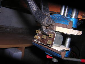
6-Removing the relay cover
The best tool I could find was a pair of thin pincers.Tools: Pincers
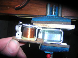
7-Relay cover removed
8-Doing the same test as above with the cover off
Reveals that contact is not made properly, but applying a very slight pressure on the blade makes it.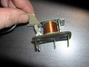
9-Cleaning the contact was useless
Because the contact was not made anyway.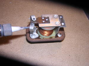
10-Adding a thin coat of solder was necessary
To gain extra thickness on C1 contact point. Be extremely careful if you do so. Because my soldering tip was too thick, a first attempt resulted into soldering C1-C2-C3 together ! I was lucky to avoid disaser by using a solder sucker!Tools: Soldering iron
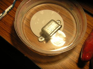
11-Meanwhile the relay cover was having a citric acid bath
It is not at all necessary... pure cosmeticsI got the idea from this excellent Jaguar E-Type site.
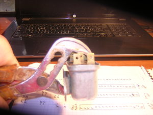
12-Puting the cover back in place
Tools: Pliers

