
Relay box and printed circuit : accessing
On SRH cars the relay box is located on the right handside of the engine, under the fan and the voltage regulator. The point of removing this part is checking the relays, the connectors and the contacts on the printed board.
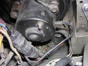
0-Remove the fan motor leads, mark on motor side
Cut the battery off. It is important to mark the wirings on the motor side : a green/yellow wire goes to the positive and a black wire located at the opposite site of the motor goes to the ground. There is also an earth strap that will need to be removed further.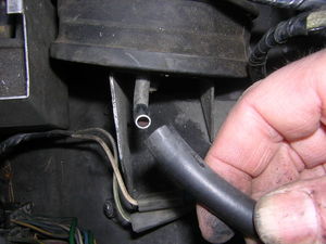
1-Remove the speed control unit hose
This is done in order to gain access to one of the three nuts securing the fan motor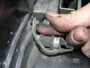
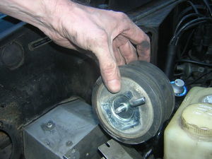
2-Remove the fan motor
The motor is secured to the bulkhead by three 9mm nuts located. The topmost is also holding an earth strap that you need to remove.Tools: 9mm open spanner
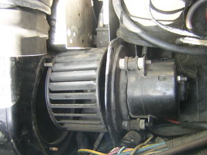
3-Ease out the fan motor
Once the three nuts and their washers have been witdrawn, gently slide the motor out avoiding to spoil the foam seal.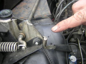
4-Remove the earth strap located on top of the air ducting
This earth strap is secured to the bonnet hinges.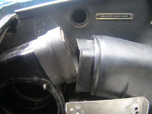
5-Remove the air duct
Just pull it off.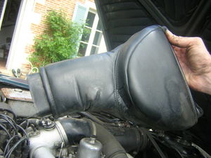
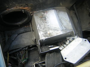
6-Air duct removed
You now have access to the relay box
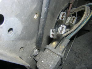
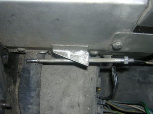
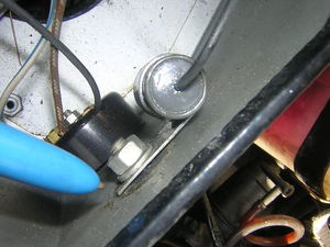
7-Mark the wirngs and remove the voltage regulator
The regulator is secured by two tiny 8mm setscrews located on both sides. Mark the wiring before disconnecting.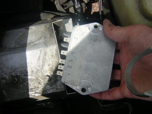
8-Regulator disconnected
Temporarily remove the cruise control bellows
This is done in order to remove the two metal covers that are fastened at the front of the relay box.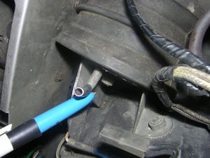
9-Remove the 11mm - 7/16 in. fastener located at the middle of the bellow
Tools: 11mm - 7/16 in. socket
10-Remove the bellows
Just slide them out. Be careful not to remove the cruise control chain unless you precisely mark its position on the throttle linkage.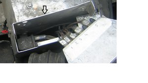
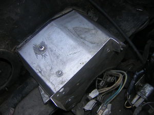
11-Remove the metal cover protecting the front part of the relay box
This metal protects a relay secured on the outside of the relay box. It is held in place by four 8mm setscrews, one of them marked on the picture by a red arrow.Tools: 8mm socket
12-Remove the relay secured to the front face of the relay box
This relay is held in place by two philips screws. Mark the wirings before removal.Tools: Philips screwdriver
13-Relay box freed form external covers / relays
The next step is to perform is detaching the relay box from the bulkhead
The relay box is secured to the bulkhead by four fasteners. Two of them are long horizontal spindles to be accessed on both sides of the box. The two others are vertical little nuts located at the bottom front of the box on both sides. The two horizontal spindles have to be removed firts.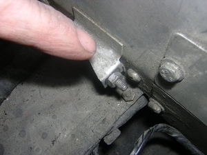
14-Locate the two horizontal spindles
Note they do not have the same length, the left one (facing the engine) is longer.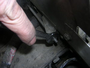
15-Turn the nut counterclockwise until it pivotes the whole spindle
and carry on doing so, the spindle will progressively come out of the bulkheadTools: 9mm open spanner
16-Slide the spindle away frontwards
Follow the same last steps for the other spindle
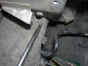
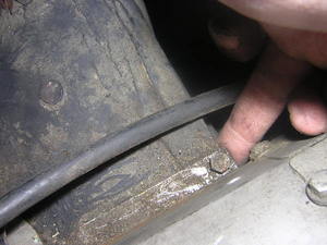
17-Locate the left securing nut, easily accessible at the bottom of the box and remove it
Prior to removing the right handside nut , you must remove the duct drain tube
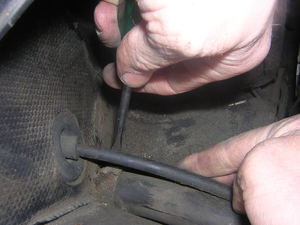
18-Remove the duct drain tube clamps
This tube is sitting under the speedometer cable.Tools: Flat screwdriver
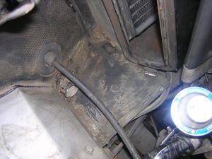
19-Duct drain tube removed
20-Locate the right securing nut and remove it
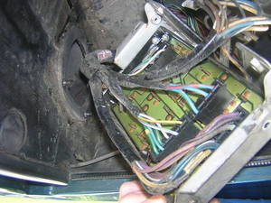
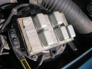
21-Slide the relay box forward and twist it upside down
Be careful and do gently because the box is not disconnected yet from the looms.Relay box structure
The relay box consists of a cover and a printed board. These two parts are secured together by four setscrews accessible from under the printed board frame. Two elements : a Scintilla switch and a 20mf condenser are secured to the box cover and thus have to disconnected before detaching the cover from the board.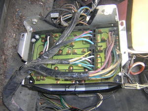
22-Remove the four 8mm nuts securing the printed board to the cover
These nuts are horizontal yo find them at each corner of the board frame.Tools: 8mm open spanner
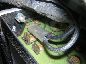
23-Close view of one of the nuts securing the board to the cover on the relay box
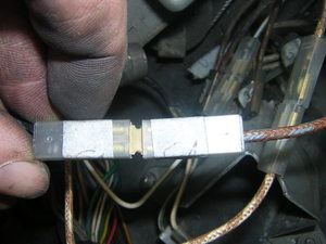
24-Remove the Scintilla switch and the condenser from the cover
This can be done using 8mm, 12mm spanners and a flat screwdriver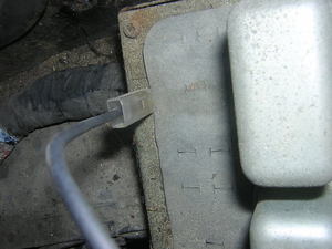
25-Disconnect the Scintilla lead to the board
26-Do not disconnect the Scintilla from its condenser
The connectors are not intended for this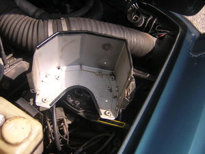
27-Remove the relay box cover
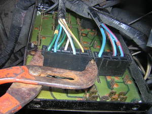
28-Gently disconnect all of the five connectors
Using pliers, very gently twist them until they disconnect.Tools: Pliers
29-Printed board fully released with relays still plugged in
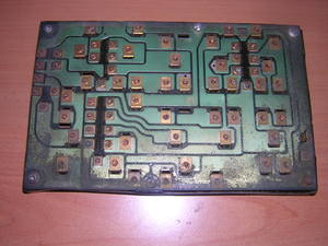
30-Printed circuit with paper and relays removed

