
Coolant : Repair the coolant level sensor amplifier
This is entirely based on an article by Brian Vogel, on the English RR Forum. Every detail is fully explained in Brian's article, so please refer to this article. This page is only here to show the main steps in pictures.
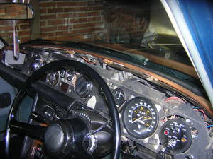
0-Remove the top roll
See here how to perform.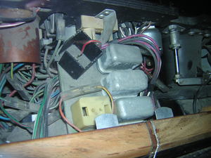
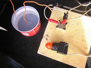
1-The amplifier is located in the middle, on a relay board
It is the white plastic box on the picture.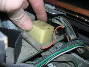
2-Carefully remove the amplifier
Especially because it is surrounded with tiny and fragile electronic devices (you can notice some of them at the rear)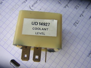
3-Coolant amplifier removed
4-Test the amplifier
To perform the test, see Brian's article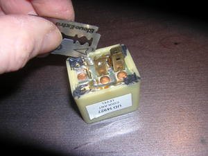
5-Remove the amplifier cap
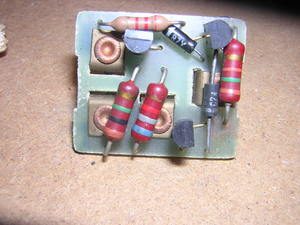
6-Remove the two diodes and the three transistors from the board
In other words every black item that is soldered on the board. On the picture you can see the three transistors and the two diodes.Tools: Solder sucker
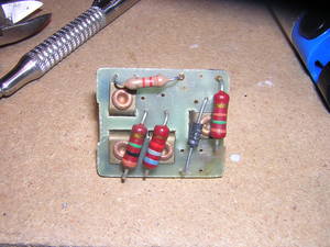
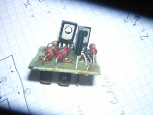
7-Almost done
This is the board with almost every part removed minus one rectifier diode (the black one).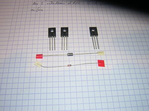
8-These componants did work ok in my case
Top left :2 STMicroelectronics BD138 PNP - SOT-32 I transistors
Top right :
1 STMicroelectronics BD139 NPN - SOT-32 I(C) transistor
Second row : 1 universal diode - 1N Taiwan Semiconductor 1N4007
Bottom : 1 zener diode - Fairchild Semiconductor 1N5233BTR DO-35 Tension Zener: 6 V
Total cost less than 1 € at Conrad
9-Here is the board with the new parts soldered at the right place
Once again, refer to the article by B. Vogel to make sure the transistor legs especially are at the right place
